Symbols#
Original schematic symbols and example circuits for the
electronics section. Passives and discrete parts follow IEC /
IEEE notation; integrated modules without a standard glyph are
drawn as labeled blocks. All SVGs inherit the page color via
currentColor.
Standard Symbols#
Symbol |
Component |
|---|---|
|
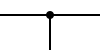
Wire and junction. Plain line is a conductor; a filled dot at a crossing marks a soldered connection. Crossings without a dot pass over each other. |

|
Ground. Three horizontal lines tapering downward. The reference rail every voltage measurement implicitly subtracts from; chassis, earth, or signal ground depending on the variant. |

|
Battery (cell). Long line is the positive terminal, short line the negative. Stacked pairs make a multi-cell battery; the symbol scales with cell count. |
|
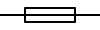
Fuse. Rectangle straddling a straight wire. The wire opens when current exceeds the rating; sacrificial protection for everything downstream. |
|
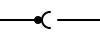
Connector (plug and jack). Filled dot (plug) seated in a half-circle pocket (jack). One half of every removable interface. |
|
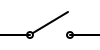
Switch. Two terminals broken by a hinged lever. Shown open; rotated down it closes the circuit. |
|
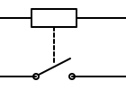
Relay. Coil on top, contacts on the bottom, dashed line marking the mechanical link. Energising the coil moves the contacts. |
|
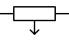
Solenoid. Coil rectangle with an arrow-tipped plunger extending out. Energising the coil pulls the plunger; the motive force behind doorbells, lock strikers, and pick-gun hammers. |
|
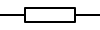
Resistor. Two-terminal passive that opposes current flow. Rectangle is the IEC form; the IEEE zigzag is an equally valid alternative. |

|
Capacitor. Two parallel plates separated by a dielectric. Stores energy in an electric field; passes AC, blocks DC. |
|
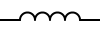
Inductor (coil). Series of arcs between two leads. Stores energy in a magnetic field; resists changes in current. |
|
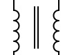
Transformer. Two coils on a shared core (the parallel vertical bars). Coupled by mutual induction; the turns ratio sets the voltage ratio. |

|
Moving coil meter. Circle with the quantity inside, A for ammeter and V for voltmeter. Series for current, parallel for voltage. |

|
Microphone. Circle with a vertical diaphragm bar. Captures acoustic pressure as a small AC signal. |

|
Speaker. Rectangle (voice coil) joined to a trapezoid (cone). Drives a cone in a magnetic gap. |

|
Piezo element. Two leads onto a capacitor-like pair of plates with a filled element between them. Generates voltage when flexed and flexes when driven; the dual-use transducer behind buzzers and contact mics. |

|
Antenna. Diverging Y from a single feed line. Cut to a fraction of the wavelength; the indispensable last hop in any wireless link. |
|
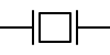
Quartz crystal. Two leads, two plates, a rectangle of quartz between them. Sets the carrier in a transmitter and the clock in any micro; the slab’s mechanical resonance defines the frequency. |
Semiconductors#
Symbol |
Component |
|---|---|
|
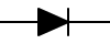
Diode. One-way current valve. The triangle points in the direction of conventional current flow; the bar is the cathode. |
|
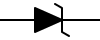
Zener diode. Diode with a Z-shaped cathode bar. Held reverse-biased as a voltage reference; the bar’s hooks distinguish it from a generic diode. |
|
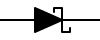
Schottky diode. Diode with a squared-S cathode bar. Metal-semiconductor junction; lower forward voltage and faster switching than a PN junction. |
|
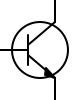
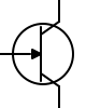
Bipolar transistor (NPN). Vertical base bar with collector and emitter leads angled out. Arrow on the emitter points away from the base for NPN, toward it for PNP. |
|
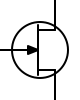
JFET (N-channel). Vertical channel bar with the gate joining at a right angle. Arrow on the gate points into the channel for N-channel, out for P-channel. |
|
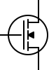
MOSFET (N-channel enhancement). Gate separated from the channel by a small gap (the gate oxide). Three short bars on the channel mark enhancement mode; one continuous bar marks depletion. |
|
Unijunction transistor. Base bar with the emitter joining at an angle. Arrow on the emitter; only one PN junction. |
|
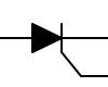
SCR. Diode with an extra gate lead off the cathode bar. Latches on when the gate is pulsed; turns off only when current falls to zero. |
|
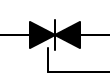
Triac. Two SCRs in antiparallel sharing a single gate. Two pairs of triangles point away from a central bar; conducts in both directions. |
|
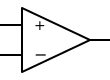
Operational amplifier. Triangle with inverting (−) and non-inverting (+) inputs on the left, output at the apex. |
Photonics#
Symbol |
Component |
|---|---|
|
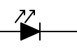
LED. Diode with two arrows pointing away, marking emitted radiation. Forward-biased junction; the workhorse status indicator and visible-light source. |
|
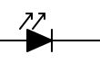
IR LED. LED in the 850–950 nm band. Same symbol as a visible LED; the operator labels which one by wavelength. |
|
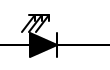
Laser diode. Diode with three arrows. The polished cavity produces stimulated, coherent emission; the extra arrows mark the intensity. |
|
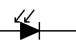
Photodiode. Diode with arrows pointing toward it (absorption). Reverse-biased junction; incident photons release a current. |
|
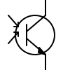
Phototransistor. BJT with arrows pointing at the base region. The base junction acts as the photodiode; the transistor adds gain. |
|
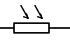
LDR. Resistor with arrows pointing at it. Cadmium-sulphide cell whose resistance falls with light. |
|
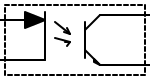
Optocoupler. LED and phototransistor in a dashed enclosure marking galvanic isolation. Input and output share no electrical path; only photons cross. |
|
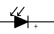
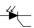
Solar cell. Photodiode marked with a “+” to indicate it sources current rather than sensing it. Same junction, optimized for area and power. |
|
Photothyristor. SCR with arrows pointing at the junction. The light pulse triggers the gate; the device latches on. |
Modules#
Sensor modules and integrated parts without a standard schematic symbol. The drawings here are labeled blocks with conventional pinouts, useful for placing the part in a circuit diagram without claiming a specific internal topology.
Symbol |
Component |
|---|---|
|
Gyro. Angular rate sensor. Reports rotation about each axis; MEMS variants are tiny and cheap. |
|
Accelerometer. Linear acceleration sensor. Detects gravity and motion; pair with a gyro for an IMU. |
|
GPS. Satellite positioning module. NMEA out, antenna in, fix in tens of seconds. |
|
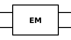
EM sensor. Electromagnetic field sensor. Magnetometer, Hall, or fluxgate. |
|
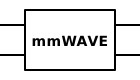
mmWave radar. 24–77 GHz radar. Detects motion, presence, and velocity through plastic and clothing. |
|
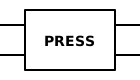
Pressure sensor. Barometric, gauge, or differential. Piezoresistive or capacitive element. |
|
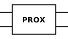
Proximity sensor. Non-contact detection. Inductive, capacitive, or optical; reports presence within range. |
|
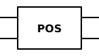
Position sensor. Potentiometer, encoder, LVDT, or resolver. Absolute or incremental position. |
Example Circuits#
Voltage Divider#
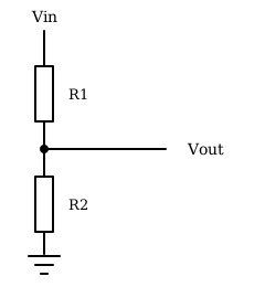
Two resistors in series across Vin; Vout is taken from
the midpoint. Output scales as Vout = Vin * R2 / (R1 + R2).
The substrate behind every potentiometer, reference rail, and
analogRead calibration.
Op-Amp Inverting Amplifier#
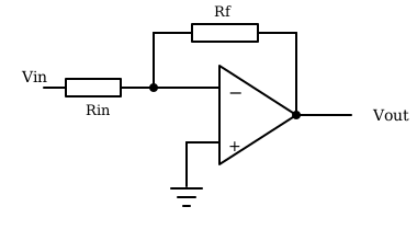
The classic feedback amplifier. Vin drives the inverting
input through Rin; the output feeds back through Rf;
the non-inverting input ties to ground. Closed-loop gain is
Vout / Vin = -Rf / Rin.
References#
IEC 60617, Graphical symbols for diagrams.
IEEE Std 315-1975 (R1993), Graphic Symbols for Electrical and Electronics Diagrams.
Components for the passive components shown.
Semiconductors for the diode and transistor families.
Photonic Semiconductors for the LED, photodiode, and optocoupler families.
Analog Integrated Circuits for op-amp circuits.